
CEM
3D Electromagnetics
Rectangular Waveguide (WR-90)
Driven TE₁₀ Transmission in X-Band with the Palace Finite-Element Solver
Explore GPU-accelerated computational electromagnetics (CEM) powered by NumericalAI and the open-source Palace 3D finite-element solver. This example drives a standard WR-90 rectangular waveguide — the workhorse plumbing of X-band radar and microwave systems — with numeric wave ports and extracts its scattering parameters.
An air-filled metal tube with a 22.86 × 10.16 mm cross-section is excited at one end and terminated at the other, both with mode-matched wave ports. Across the 10–12 GHz band the guide carries a single, clean TE₁₀ mode with almost no reflection — the textbook picture of dominant-mode propagation.
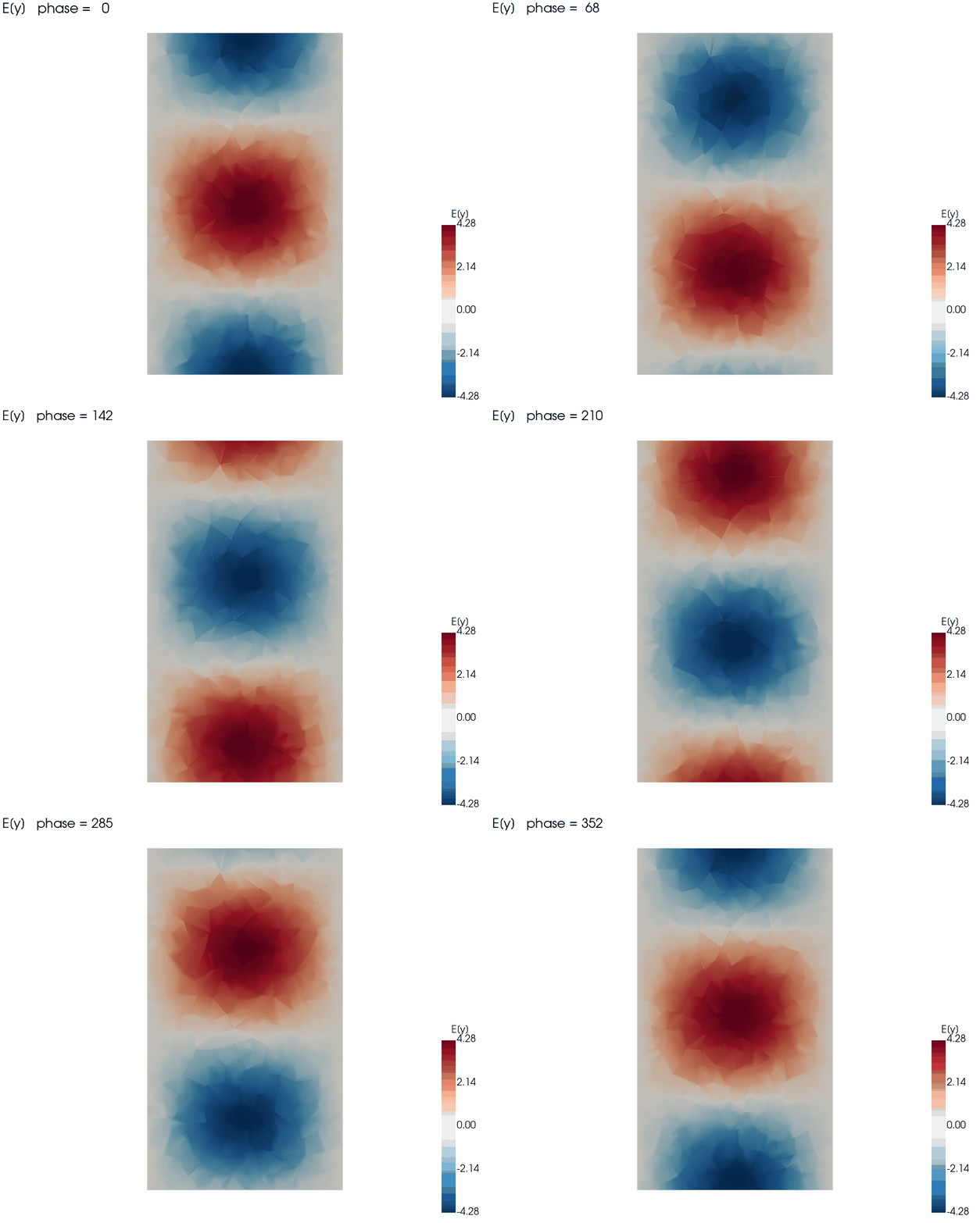
Vertical Electric Field E(y) — TE₁₀ Mode
The field animates over one phase cycle as the wave travels down the guide. The single half-sine lobe across the broad wall — maximum at the center, vanishing at the side walls — is the signature of the dominant TE₁₀ mode.
Scattering Parameters
< −44 dB
Return Loss |S₁₁|
~0 dB
Insertion Loss |S₂₁|
TE₁₀
Single Propagating Mode
| Frequency (GHz) | |S₁₁| (dB) | |S₂₁| (dB) |
|---|---|---|
| 10.0 | −58.4 | −0.001 |
| 11.0 | −46.0 | −0.002 |
| 12.0 | −44.3 | −0.003 |
Return loss below −44 dB means essentially all incident power is transmitted (|S₂₁| ≈ 0 dB) with negligible reflection — the expected behavior of a well-matched, lossless air-filled guide. The stored electric and magnetic energies are nearly equal, confirming a clean traveling wave.
Simulation Configuration
Geometry & Mesh
Standard:
WR-90 (X-band)
Cross-section:
22.86 × 10.16 mm
Length:
40 mm
Mesh Elements:
~9,000
Degrees of Freedom:
~12,500
Excitation & Frequency
Analysis Type:
Driven (freq. domain)
Band:
10 – 12 GHz
Ports:
2 numeric wave ports
Mode:
TE₁₀ (dominant)
Fill:
Air / vacuum
Solver
Problem type:
Driven
Basis:
Nédélec (H-curl)
Port de-embedding:
Modal wave port
Frequency points:
3
Precision:
Double
Boundary Conditions
Four side walls:
Perfect electric conductor (PEC)
Port 1 (z = 0):
Wave port — TE₁₀ excitation
Port 2 (z = L):
Wave port — matched termination
Computational Performance
~10 s
Wall-Clock Time
GPU
NVIDIA CUDA
12.5K
Degrees of Freedom
< −44 dB
Match Quality
The Physics of Dominant-Mode Propagation
Cutoff and Single-Mode Operation
A hollow metal guide only carries a mode above its cutoff frequency. For WR-90 the TE₁₀ cutoff is about 6.6 GHz, while the next modes stay cut off past ~13 GHz. That is exactly why X-band systems operate in the 8–12 GHz window: a single, predictable TE₁₀ mode propagates while every higher-order mode decays away, keeping the signal clean.
Why Numeric Wave Ports?
A wave port solves a 2D eigenproblem on the port face to find the true TE₁₀ field profile, then launches and absorbs exactly that mode. This mode-matched excitation is what drives the reflection down below −44 dB — a lumped approximation could never terminate the guide so cleanly, so wave ports are the gold standard for waveguide S-parameters.
Industrial Applications
Radar & Aerospace
X-band waveguide feeds, runs, and transitions for airborne and ground radar, where low loss and precise mode control are essential.
Satellite & Communications
Feed networks, filters, and orthomode transducers for satellite up/downlinks built on rectangular-waveguide plumbing.
Components & Test
Baseline S-parameters for waveguide couplers, bends, tapers, and calibration standards before machining and bench measurement.
Solver Validation
A closed-form benchmark: analytic TE₁₀ cutoff and impedance make this an ideal check of wave-port accuracy for any CEM workflow.
Why NumericalAI for Electromagnetics
Powered by Palace — AWS's open-source, GPU-accelerated 3D finite-element solver for full-wave electromagnetics
Mode-accurate wave ports — true modal excitation and de-embedding for trustworthy waveguide S-parameters
Driven, eigenmode, and adaptive sweeps — one platform for the full microwave-design workflow
Cloud GPUs on demand — sub-minute solves with no local HPC cluster or solver installation
Business Value & ROI
NumericalAI brings production-grade electromagnetic simulation to an intuitive cloud interface — no solver installation, no cluster administration, no meshing bottleneck.
Design with confidence: verify match, loss, and mode purity of waveguide components in seconds, catching problems long before anything is machined.
Ready to Simulate Your Waveguide?
Run full-wave, wave-port electromagnetic simulations with Palace on NumericalAI. Upload your Palace config.json and mesh, and get S-parameters and fields on cloud GPUs.
AI-Assisted GPU-Powered Simulations
© 2026 NumericalAI, all rights reserved. |Privacy Policy |Terms of Service |Executive brief |CEM vs HFSS |FAQ