
CEM
3D Electromagnetics
Eigenmodes of a High-Q Dielectric Resonator
A Shielded Dielectric Puck with a Lumped-Port Junction, Solved with the Palace Finite-Element Solver
Explore GPU-accelerated computational electromagnetics (CEM) powered by NumericalAI and the open-source Palace 3D finite-element solver. A dielectric resonator stores microwave energy in a small puck of high-permittivity ceramic, reaching quality factors that rival — and often beat — bulky metal cavities. Designing one means knowing, before you machine anything, exactly where it resonates and how sharp that resonance will be. An eigenmode analysis finds those natural frequencies and field patterns directly from the geometry, no drive signal required, by solving the source-free curl-curl eigenproblem.
This example models a high-permittivity dielectric puck (εr = 38) suspended in a shielded, perfectly conducting cavity. A single lumped port stands in for a linearized Josephson junction, letting Palace report the Energy Participation Ratio (EPR) of the junction alongside each mode. The result is a full-wave picture of a trapped resonance — the foundation for predicting resonator frequency, dielectric-limited quality factor, and how strongly a qubit or drive couples to it.
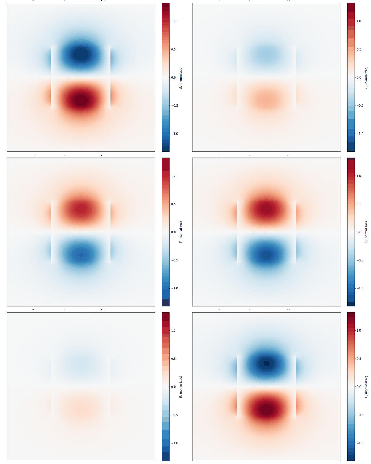
Fundamental mode (6.133 GHz): the in-plane electric field Eₓ on a slice through the puck, animated over a full phase cycle. The dipolar pattern is tightly confined to the high-permittivity dielectric.
What the Model Represents
A Puck That Traps the Field
The resonant element is a small block of high-permittivity dielectric(εr = 38) with a very low loss tangent (tan δ = 1×10⁻⁴), sitting inside an air-filled, perfectly conducting box. The large permittivity contrast acts like a soft mirror: it traps the electromagnetic field inside the puck, so the mode barely touches the metal walls. That confinement is exactly what gives a dielectric resonator its compact size and very high quality factor.
A Junction as a Lumped Port
A single lumped port — a linearized junction inductance of L = 1 nH across the port face — represents where a Josephson junction or a drive line would attach. With this port in place, Palace reports the Energy Participation Ratio of each eigenmode: the fraction of the mode's inductive energy stored in the junction. It is the bridge between a passive full-wave field solve and a circuit-level, quantized description of the resonator.
Simulation Configuration
Geometry & Mesh
Structure:
Puck in shielded cavity
Cavity size:
20 × 20 × 10 mm
Length unit:
mm (L₀ = 1e-3)
Mesh:
Tetrahedral (~7,057 elem.)
Element order:
3
Dielectric Puck
Permittivity εᵣ:
38.0
Permeability µᵣ:
1.0
Loss tangent:
1×10⁻⁴
Puck size:
8 mm block
Surrounding region:
Vacuum, εᵣ = µᵣ = 1.0
Solver
Problem type:
Eigenmode
Eigenpairs:
6 solved / 3 saved
Shift target:
4.0 GHz
Inner solver:
GMRES (GPU)
Tolerance:
1e-8
Boundary Conditions
Lumped port (×1):
L = 1 nH linearized junction, direction +X (EPR)
Metal:
PEC (perfectly conducting cavity walls)
Postprocessing:
Per-domain energy + field probe at cavity center
Computational Setup
6.13 GHz
Fundamental Mode
~10,200
Quality Factor Q
~47 s
GPU Solve Time
140k
Degrees of Freedom
Resonator & Result Parameters
| Parameter | Value | Role |
|---|---|---|
| Dielectric permittivity εᵣ | 38.0 | High contrast traps the field inside the puck |
| Loss tangent tan δ | 1×10⁻⁴ | The dominant, intrinsic loss channel |
| Junction inductance L | 1 nH | Linearizes the junction for the EPR port |
| Fundamental frequency | 6.133 GHz | Lowest computed eigenmode |
| Quality factor Q | ~10,215 | Dielectric-loss limited (see below) |
| Dielectric energy participation | 97.9% | Fraction of electric energy inside the puck |
| Junction EPR p | 2.3×10⁻⁴ | Inductive energy fraction at the junction |
Palace targets the lowest modes near a 4 GHz shift; the fundamental of this puck lands at 6.133 GHz, isolated more than 1.5 GHz below the next (near-degenerate) mode pair at ~7.64 GHz. The very low loss tangent is what makes high-permittivity ceramics a workhorse choice for high-Q microwave resonators.
Reading the Physics
Energy Confinement in the Puck
Palace's per-domain energy postprocessing shows that 97.9% of the mode's electric energy sits inside the dielectric, with barely 2% leaking into the surrounding vacuum. That is the defining signature of a dielectric resonator: the high permittivity behaves like a set of open mirrors, holding the field in a volume far smaller than a free-space half-wavelength. The animated Eₓ map makes this visible — the dipolar field is packed into the puck and decays quickly outside it.
Why the Q Is Dielectric-Limited
Because almost all the energy lives in the lossy ceramic, the resonator's quality factor is set by the material, not the metal. The dielectric-limited estimate Q ≈ 1 / (p · tan δ) with participation p = 0.979 and tan δ = 1×10⁻⁴ gives Q ≈ 10,200 — essentially identical to the full-wave eigen-Q of 10,215. That agreement confirms the loss budget is dominated by dielectric absorption, and it tells a designer exactly which knob to turn: a lower-loss ceramic, or a geometry that pushes more field into vacuum, directly buys a higher Q.
From Fields to a Circuit: EPR
The lumped-port Energy Participation Ratio (p ≈ 2.3×10⁻⁴ for the fundamental) quantifies how much of the mode's inductive energy is concentrated at the junction. This single number links the full-wave solve to a quantized circuit model: it sets the anharmonicity a transmon inherits from the mode and the strength of qubit–resonator coupling — the essential ingredients for turning a passive cavity into a usable quantum element.
Where This Applies
Filters & Oscillators
Dielectric resonators set the frequency of low phase-noise oscillators and the poles of compact, high-selectivity RF and microwave filters used throughout base stations and radar.
Quantum Memories & Cavities
High-Q dielectric and 3D cavities store quantum states and couple to transmons; the EPR port turns an eigenmode solve into the anharmonicity and coupling a circuit model needs.
Loss & Material Characterization
Because the Q is dielectric-limited, the same workflow extracts loss tangents from measured resonances — a standard way to qualify low-loss ceramics and substrates.
Readout & Purcell Filters
Extend the workflow to readout resonators and Purcell filters, where knowing the mode frequency, Q, and participation is what protects qubit lifetime during measurement.
Why NumericalAI for High-Q Resonators
Powered by Palace — AWS's open-source, GPU-accelerated 3D finite-element solver for full-wave electromagnetics
High-order elements — order-3 basis functions resolve tightly confined, high-Q modes accurately with far fewer elements
Lumped-port junctions & EPR — connect a full-wave field solve to a quantized circuit model in a single run
Per-domain energy postprocessing — participation ratios and dielectric-limited Q, the metrics that matter for coherence, on cloud GPUs
Business Value & ROI
NumericalAI brings production-grade electromagnetic simulation to an intuitive cloud interface — no solver installation, no cluster administration, no meshing bottleneck.
Design with confidence: pin down a resonator's frequency, quality factor, and energy participation in a single GPU run, so you can trade off material, size, and coupling on screen instead of on the bench.
Ready to Model Your Resonator?
Run full-wave eigenmode simulations of dielectric resonators and cavities with Palace on NumericalAI. Upload your Palace config.json and mesh, and get mode frequencies, quality factors, and field maps on cloud GPUs.
AI-Assisted GPU-Powered Simulations
© 2026 NumericalAI, all rights reserved. |Privacy Policy |Terms of Service |Executive brief |CEM vs HFSS |FAQ