
CEM
3D Electromagnetics
Resonant Modes of a Cylindrical Cavity
Closed PEC Resonator vs Floquet Periodic Cell with the Palace Finite-Element Solver
Explore GPU-accelerated computational electromagnetics (CEM) powered by NumericalAI and the open-source Palace 3D finite-element solver. An eigenmode analysis finds the natural resonant frequencies and field patterns of a structure — no source required — by solving the source-free curl-curl eigenproblem.
This example runs the same dielectric-filled cylindrical cavity two ways. The first closes it with perfect electric conductor (PEC) walls — the textbook resonator. The second replaces the end caps with a Floquet periodic boundary, turning the cavity into the unit cell of an infinite periodic structure and computing its modes at a prescribed inter-cell phase shift — the workflow behind phased arrays and band diagrams.
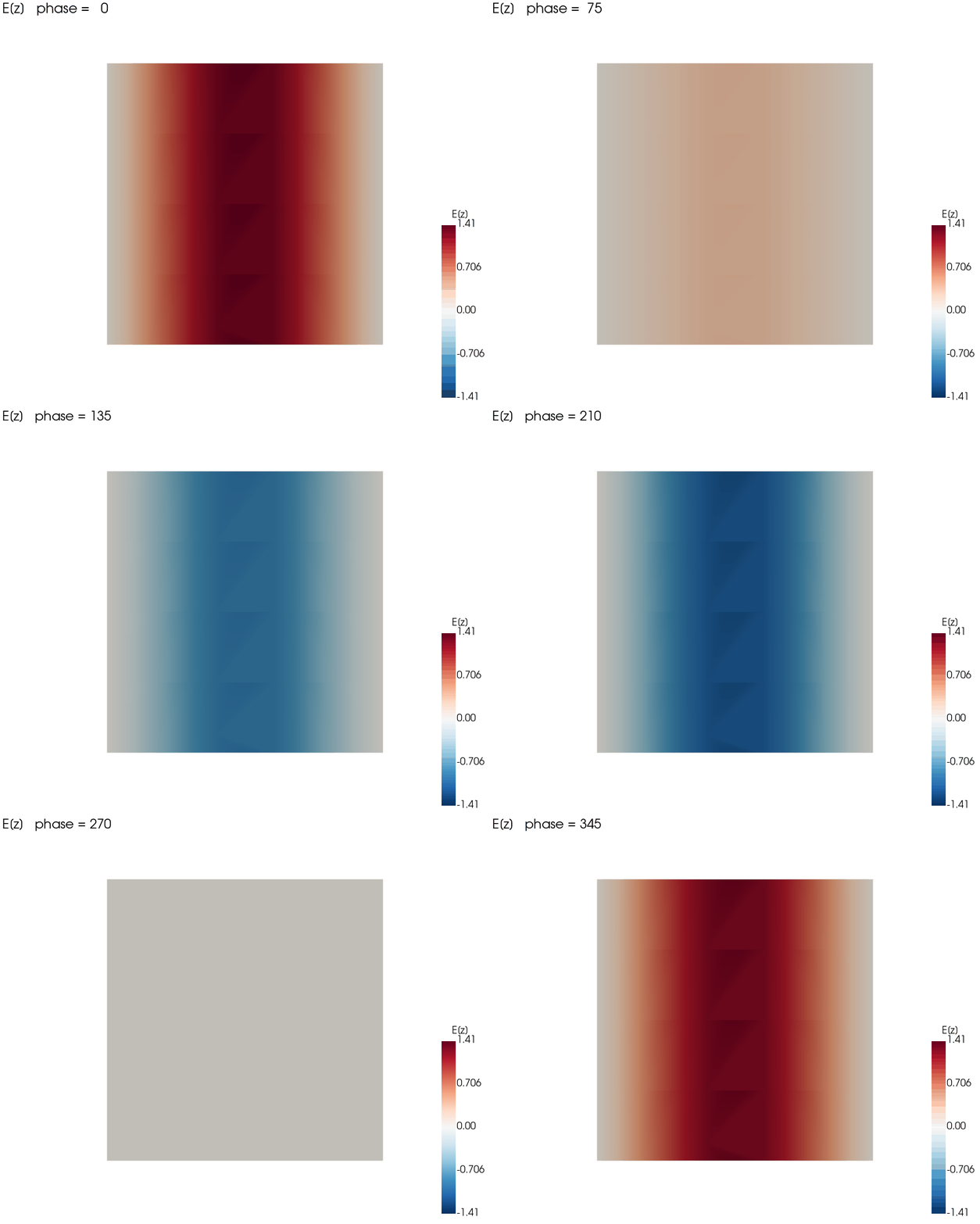
PEC cavity — E(z), fundamental mode
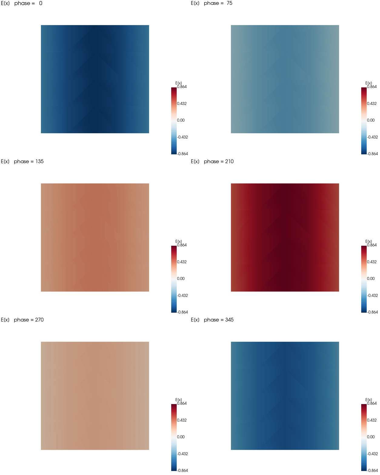
Floquet cell — E(x), fundamental mode
Two Boundary Treatments
PEC Walls (Closed Resonator)
All walls and end caps are perfect electric conductors, so the cavity is sealed and its modes are the classic lossless resonances (real frequencies) of a closed dielectric resonator. Meshed with hexahedra; the solver targets the fundamental TE₁₁₁ band near 2.9 GHz. This is the validation baseline.
Floquet Periodic Cell
The two end faces are linked by a Floquet–Bloch condition, E(r + a) = E(r) e−j k·a, with wave vector [0, 0, 0.2]. The side wall stays PEC. This models one cell of an infinite periodic waveguide; sweeping the phase shift traces the dispersion (band) diagram. Meshed with tetrahedra.
How Periodicity Reshapes the Spectrum
Each tick is one computed eigenfrequency. Closing the cavity with PEC walls fixes the fundamental at 2.905 GHz; imposing the Floquet phase shift lowers it to 2.320 GHz and rearranges the higher modes — exactly the information a band-diagram study extracts, one phase point at a time.
Lowest Resonant Frequencies
| Mode | PEC (GHz) | Floquet (GHz) | Quality factor Q |
|---|---|---|---|
| 1 | 2.905 | 2.320 | ~2,500 |
| 2 | 2.923 | 2.320 | ~2,500 |
| 3 | 2.923 | 2.978 | ~2,500 |
| 4 | 3.469 | 3.747 | ~2,500 |
| 5 | 4.148 | 3.747 | ~2,500 |
Q ≈ 2,500 for every mode, set by the dielectric loss tangent (tan δ = 0.0004 → Q = 1/tan δ). Repeated PEC frequencies are degenerate mode pairs from the cavity's rotational symmetry.
Simulation Configuration
Geometry & Mesh
Structure:
Cylindrical cavity
PEC mesh:
Hexahedral
Floquet mesh:
Tetrahedral
Length unit:
cm (L₀ = 1e-2)
Element Order:
4
Material Fill
Permittivity εᵣ:
2.08
Permeability μᵣ:
1.0
Loss tangent:
0.0004
Implied Q:
~2,500
Solver
Problem type:
Eigenmode
Eigenpairs:
15
Target:
2.0 GHz
Inner solver:
GMRES + multigrid
Tolerance:
1e-8
Boundary Conditions
PEC run:
All walls + end caps = PEC
Floquet run:
End faces periodic (k = [0,0,0.2]); side wall PEC
Computational Performance
~24 s
PEC Run
~48 s
Floquet Run
GPU
CUDA Device
order 4
High-Order FEM
Reading the Physics
Degeneracy & Symmetry
Several PEC modes appear as near-identical pairs (2.923, 4.148, 4.397, 4.628 GHz…). These are degenerate modes: the cylinder's rotational symmetry allows two orthogonal field orientations at the same frequency. Recovering the correct multiplicities is a stringent check on the eigensolver's accuracy — here the backward error sits at the 10⁻¹² level.
Quality Factor from Dielectric Loss
With ideal PEC walls the only loss is in the fill, so every mode reports the same Q ≈ 2,500 — precisely 1/tan δ for the 0.0004 loss tangent. Swap in lossy metal walls (an impedance boundary) and Q would drop and vary per mode, which is how real resonator budgets are built.
Industrial Applications
Cavity & Dielectric Filters
Predict resonant frequencies and quality factors for microwave cavity and dielectric resonator filters before machining hardware.
Phased Arrays & Metamaterials
Unit-cell analysis with Floquet boundaries yields scan-angle behavior and dispersion diagrams for periodic antennas and metasurfaces.
Periodic Waveguides
Band structure of slow-wave and corrugated waveguides, where the inter-cell phase shift is imposed directly through the Floquet condition.
Quantum & Accelerator Cavities
High-Q mode and frequency prediction for superconducting readout cavities and accelerator structures.
Why NumericalAI for Electromagnetics
Powered by Palace — AWS's open-source, GPU-accelerated 3D finite-element solver for full-wave electromagnetics
Eigenmode solver — resonant frequencies, quality factors, and mode shapes, including degenerate multiplicities
Periodic & Floquet boundaries — unit-cell modeling and band diagrams for periodic structures
High-order elements on hex or tet meshes — accurate spectra with fewer unknowns, on cloud GPUs
Business Value & ROI
NumericalAI brings production-grade electromagnetic simulation to an intuitive cloud interface — no solver installation, no cluster administration, no meshing bottleneck.
Design with confidence: nail resonant frequencies and Q factors — and explore periodic scan behavior — in under a minute per run, before any hardware is cut.
Ready to Find Your Modes?
Run full-wave eigenmode and periodic-cell simulations with Palace on NumericalAI. Upload your Palace config.json and mesh, and get resonances and mode shapes on cloud GPUs.
AI-Assisted GPU-Powered Simulations
© 2026 NumericalAI, all rights reserved. |Privacy Policy |Terms of Service |Executive brief |CEM vs HFSS |FAQ